NOTE: Before moving into this example it is very necessary to know about the device registration, provisioning and converting the ESP32 device into an EzloPi device along with knowledge of Ezlogic desktop app. All these information can be collectively found in EzloPi User manual document.
Relay Circuitry and Lamp Circuit Setup.
For interfacing and controlling the lamp we will be needing following components:
- An AC lamp with lamp holder and wires to connect to AC mains.
- ESP32 device for converting it into EzloPi smart device
- A properly designed relay module
- Power source for ESP32 as well as relay module
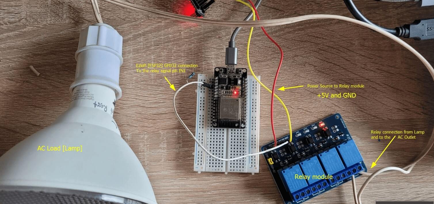
The wiring diagram can be represented as:
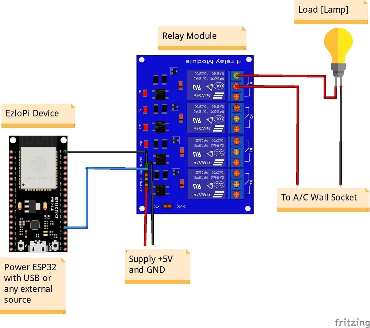
In the same way connection with the components has been made as: