


The EzloPi smart devices provide automation through simple, customizable use with our open-source EzloPi platform, making daily life easier and improving human-machine interactions.
Before moving into this example, it is very important to know about the device registration, provisioning and converting the ESP32 device into an EzloPi device along with knowledge of Web Flasher, MiOS Mobile Application for Android/iOS and the MiOS Web Application.
1. About this example
The following project integrates the TLS2561 luminosity sensor with the EzloPi device to enable precise light measurement in various environments. By interfacing the TLS256 sensor with the EzloPi device, we can ensure accurate readings of ambient light levels, crucial for tasks like automated lighting control, energy efficiency optimization, and security systems.
By leveraging the EzloPi's capabilities, this integration will empower users to create dynamic lighting environments that adapt to changing conditions effortlessly. Through the MiOS app, users can remotely monitor the light intensity value in terms of lux which will be displayed on the MiOS application dashboard.
2. Project Video Demonstration
Welcome to the project demonstration video section. The following video showcases the key aspects of Accurate light measurement using TLS2561 luminosity sensor, providing a visual walkthrough of its implementation.
3. Circuit Setup & Interfacing
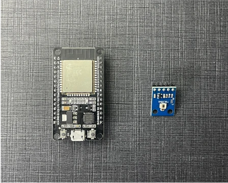
The following components are required for interfacing with the EzloPi device:
- ESP32 as an EzloPi smart device.
- TSL2561 Luminosity sensor
The wiring diagram of ESP32 30 pin is represented as follows:
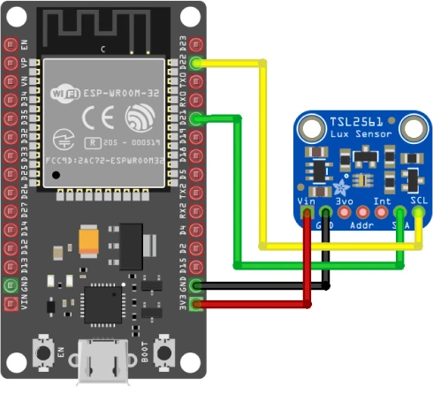
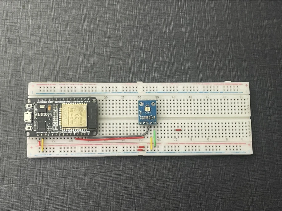
The following connections are made in order to complete the circuit setup:
From ESP32 to the TLS256 Luminosity sensor:
| ESP32 | TSL2561 |
| 3V3 | Vin |
| GND | GND |
| D21 | SDA |
| D22 | SCL |
4. Interfacing the Light/Luminosity Sensor (TSL2561) using the EzloPi Web Flasher
1. Set up your device/hardware by visiting config.ezlopi.com
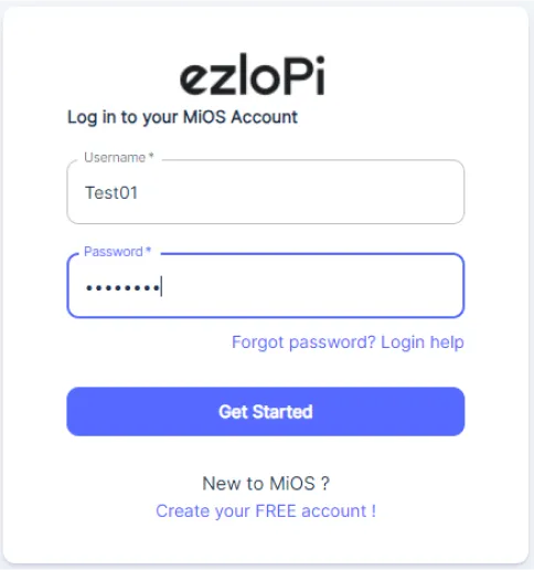
- Log in using the credentials which you just set earlier while signing up.
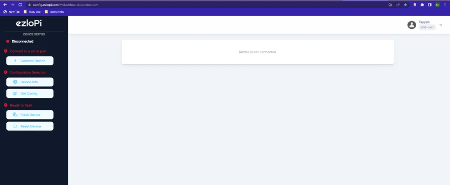
- Now, click on the Connect Device button and a pop-up window will appear.
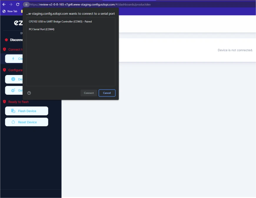
- Now, select COM Port to which your ESP32 device is connected. In our case, the COM3 port is used.
Click Connect
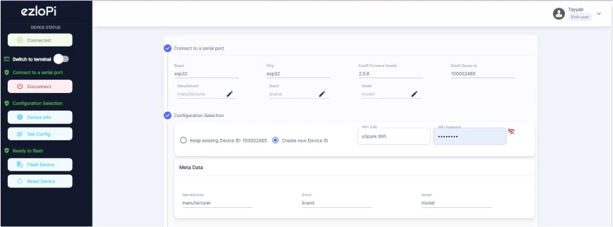
- If you are new to this and it's your first time configuring, select Create new Device ID. Enter Wifi SSID and Wifi Password.
- In the Device Configuration, tab click on I2C.
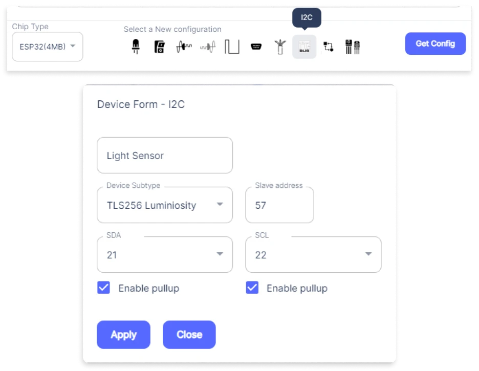
- A I2C window will open for inputting the following parameters:
- Set a device name of your choosing. In our case, we set it to Light Sensor.
- Set Device subtype to TLS256 Luminosity.
- Set Slave address to 57.
- Set SDA pin to GPIO21.
- Set SCL pin to GPIO22.Now Click the Apply button.
- After clicking the apply button you can see a table of your setting in the device configuration tab.
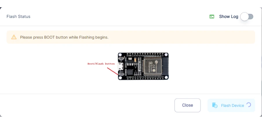
- Press the Flash Device button.
- A window will appear on the bottom right side of the screen displaying “Please press BOOT button while flashing begins.”
- Hold the BOOT button down until the next window appears on the bottom right side of the screen which says “Installation prepared. Please release the boot button now.”
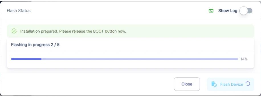
- Release the BOOT button from your ESP32 when this pop-up on the bottom right window appears.
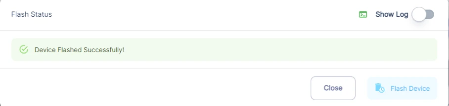
- After some time, a popup will appear saying Device Flashed Successfully! This means that your device has been set up successfully.
5. MiOS App
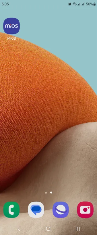
You can download the MIOS Android app from the Google Play Store and Apple App Store.


- After downloading the app, proceed to install the application and open it.
- Using the MIOS mobile application, create a new Ezlo Cloud account using the sign-up option. If you already have an account, you may proceed to log in.
- After successfully logging in, you will be able to see the number of controllers connected such as a lamp, fan, or any other device in the MiOS app. Tap on any controller of your desired ID:
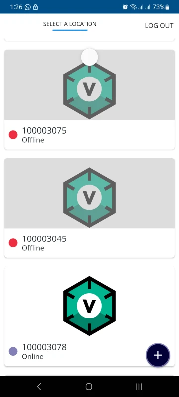
- You will be able to see the status of your controller whether it is online or offline. Access the device dashboard, and tap the device. The following view of the dashboard will appear:
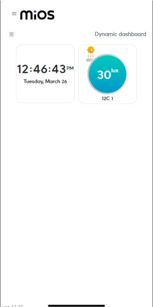
- After opening the MiOS mobile dashboard, you will be able to see the tile of your connected device, in our case the proximity sensor and neon light.
- While parking, whenever the car is away from the proximity sensor, it will not detect any motion or trigger the neon light, For now no motion is being detected.
- Similarly, it can be seen that when the car comes close to the proximity sensor, it detects motion and the neon light gets triggered. This is because of the meshbot rules we have set earlier.
6. MiOS Web Dashboard
- After configuring the controller with the EzloPi web flasher, head to ezlogic.mios.com
- Use the same credential to log in that you used for configuring the controller with the web flasher.
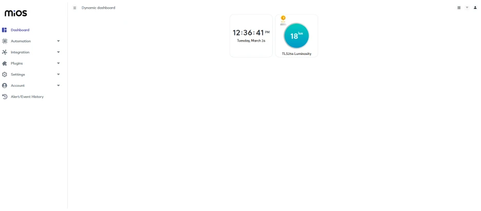
- Here, as seen in the MiOS web app above, we can see the Luminosity sensor tile. The above figure indicates that very little amount of light is being detected by the sensor as its tile shows the value of intensity of light being measured.
MeshBots:
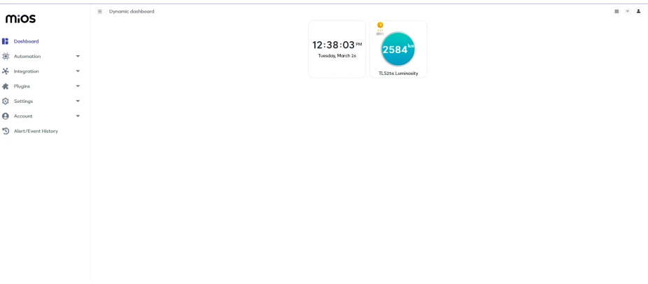
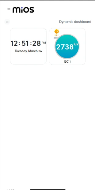
- Here, it can be seen that now more light is being detected by the Luminosity sensor, as the amount of light detected by the sensor has increased.


