


Android (section of varying length running) effect implementation by interfacing the addressable LED with the EzloPi device.
1. About this example
This project demonstrates the interfacing of the addressable LED strips, such as WS2812B, with the ESP32-based EzloPi device. This integration will enable users to control the RGB colors and implement various effects of the LED strips through the EzloPi platform such as the MiOS web and mobile applications. The addressable LED feature adds a dynamic element to smart home environments, enabling users to create immersive lighting effects tailored to different occasions or moods.
Various effects can be set up using the addressable LED strip and EzloPi device as we have demonstrated the “Android” effect in this project.
2. Project Video Demonstration
Welcome to the project demonstration video section. The following video showcases the key aspects of How to create an addressable LED with Android Effect and EzloPi, providing a visual walkthrough of its implementation.
3. Circuit Setup & Interfacing
The following components are required for interfacing with the EzloPi device:
- EzloPi device (ESP32-based controller board).
- Addressable LED strip (WS2812B).
- Power supply for the LED strip.
- Jumper wires.
- Breadboard for prototyping (Optional).
The wiring diagram is represented as follows:


The following connections are made in order to complete the circuit setup:
From Power Supply to ESP32 and LED Strip:

4. Interfacing the addressable LED strip using EzloPi Web Flasher:
Set up your device/hardware by visiting config.ezlopi.com
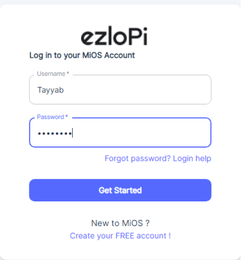
- Log in using the credentials which you just set earlier while signing up.

- Under ezloPi on the top left corner, open the drop down menu.

Select EzloPi Addressable LED.

- Now, click on Connect Device and a pop-up window will appear.

- Now, select COM Port to which your ESP32 device is connected. In our case, the COM3 port is used. Click Connect.

- If you are new to this and it’s your first time configuring, select Create new Device ID. Enter Wifi SSID and Wifi password and then click on Flash Device.

- A window will appear on the bottom left side of the screen displaying “Please press BOOT button while flashing begins.”

- Hold the BOOT button down until the next window appears on the bottom left side of the screen which says “Installation prepared. Please release the boot button now.”

- After some time, a popup will appear on the bottom right hand side of your screen saying Device Flashed Successfully!. This means that your device has been set up successfully.
5. MiOS Web Application
- After configuring the controller with the EzloPi web flasher, head to ezlogic.mios.com

- Use the same credential to log in that you used for configuring the controller with the web flasher.

- After login, click on Platforms then click on Addressable LEDs and press Configure.

- After login, click on Platforms then click on Addressable LEDs and press Configure.

- A new window will open where you can control your RGB LED strip.

- Under Effect mode, click on Android to apply this effect. By following the above steps, we can successfully implement a bicolor chase effect using addressable LEDs and the EzloPi smart device, enhancing the visual appeal and versatility of your IoT lighting setup.


