


The EzloPi smart devices provide automation through simple, customizable use with our open-source EzloPi platform, making daily life easier and improving human-machine interactions.
Before moving into this example, it is very important to know about the device registration, provisioning and converting the ESP32 device into an EzloPi device along with knowledge of Web Flasher, MiOS Mobile Application for Android/iOS and the MiOS Web Application.
1. About this example
The following project aims to integrate a DC motor with the EzloPi device for making it into a smart device, enabling users to control the motor's direction remotely through the MiOS smart app. This project provides a versatile and user-friendly solution for individuals seeking to automate and remotely manage their DC motor applications, such as blinds, curtains, or any other motorized systems by implementing meshbots to perform automation tasks on the actions or conditions set by the user.
2. Circuit Setup & Interfacing
The following components are required for interfacing with the EzloPi device:
- ESP32 as an EzloPi smart device.
- 2-channel 5V relay module.
- DC motor.
- External DC power source.
The wiring diagram for ESP32 30 pins is represented as follows:


The following connections are made in order to complete the circuit setup.
From ESP32 30 pins to 2-channel relay module:
- Connect 3V3 from the ESP32 to the VCC of the module.
- Connect GND from the ESP32 to the GND pin on the module.
- Connect D5 from the ESP32 to the IN1 pin on the module.
- Connect D4 from the ESP32 to the IN2 pin on the module.
From 2-channel relay module to the DC motor:
- Connect the COM pin of the K1 relay on the relay module to the positive terminal of the DC motor.
- Connect the COM pin of the K2 relay on the relay module to the negative terminal of the DC motor.
From 2-channel relay module to the DC supply:
- Connect the NO of the K1 relay to the NO of the K2 relay on the relay module, then connect it to the positive terminal of the DC supply.
- Connect the NC of the K1 relay to the NC of the K2 relay on the relay module, then connect it to the negative terminal of the DC supply.
3. Interfacing the 2-channel relay using the EzloPi Web Flasher
1. Set up your device/hardware by visiting config.ezlopi.com
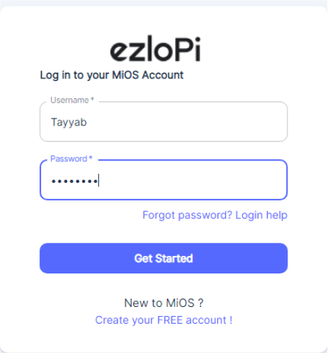
- Log in using the credentials which you just set earlier while signing up.

- Now, click on the Connect Device button and a pop-up window will appear.

Now, select COM Port to which your ESP32 device is connected. In our case, the COM3 port is used.
Click Connect.

- If you are new to this and it's your first time configuring, select Create new Device ID. Enter Wifi SSID and Wifi Password.
- In the Device Configuration, tab click on Digital Output.

- A Digital Output window will open for inputting the following parameters:
- Set a device name of your choosing. In our case we set it to Relay_1.
- Set the Out GPIO to 5.
- Set Device Subtype to Relay.
- Set Resistor to PULL UP.
- Set Default value to LOW.
- Now Click the Apply button
- In the Device Configuration, tab click on Digital Output.

- A Digital Output window will open for inputting the following parameters:
- Set a device name of your choosing. In our case, we set it to Relay_2.
- Set Device subtype to Relay.
- Set OUT GPIO to 4.
- Set Resistor to PULL UP.
- Set the Default value to LOW.
- Now Click the Apply button.
- In the Device Configuration, tab click on Digital Output.

- A Digital Output window will open for inputting the following parameters:
- Set a device name of your choosing. In our case, we set it to Relay_3.
- Set Device subtype to Relay.
- Set OUT GPIO to 15.
- Set Resistor to PULL UP.
- Set the Default value to LOW.
- Now Click the Apply button
- After clicking the apply button you can see a table of your setting in the Device configuration tab.
- Press the Flash Device button.
- A window will appear on the bottom right side of the screen displaying “Please press BOOT button while flashing begins.”

- Hold the BOOT button down until the next window appears on the bottom right side of the screen which says “Installation prepared. Please release the boot button now.”

- Release the BOOT button from your ESP32 when this pop-up on the bottom right window appears.

- After some time, a popup will appear saying Device Flashed Successfully! This means that your device has been set up successfully.
4. MiOS Web Application
- After configuring the controller with the EzloPi web flasher, head to ezlogic.mios.com
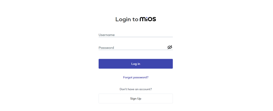
- Use the same credential to log in that you used for configuring the controller with the web flasher.

- On the MiOS web dashboard, you will be able to see the tile for all the three relays. These tiles will indicate the status of the relays and also the direction of DC Motor.
Meshbots

- On the right side of the screen under Automation, click on MeshBots.

- On meshbot screen, click on Create new MeshBot button present on the top right corner of the screen.
- After clicking on Create new MeshBot you will see this now under Automation MeshBot click on Cloud.

- On the next screen you will see that we can create a name of our choosing, in this case we write it as Test001.


- In the trigger tab you can set the TRIGGER for your device and in the ACTION tab you can set the action to be performed based on the trigger which you have created.

- Set these things in TRIGGER section:
- Set Node Type to Device.
- Set the Node to Relay_3.
- Set the Category to Switch.
- Set the value to True.

- In the TRUE part, Set these values in the ACTION section.
- Set Controllable Type to Device.
- Set the Controllable to Relay_1.
- Set the Capability to Switch.
- Set the Value to true.
- Now add another ACTION.
- Set Controllable Type to Device.
- Set the Controllable to Relay_2.
- Set the Capability to Switch.
- Set the Value to false.
- Now Click the Save button.

- In the FALSE part, Set these values in the ACTION section.
- Set Controllable Type to Device.
- Set the Controllable to Relay_1.
- Set the Capability to Switch.
- Set the Value to false.
- Now add another ACTION.
- Set Controllable Type to Device.
- Set the Controllable to Relay_2.
- Set the Capability to Switch.
- Set the Value to true.
- Now Click the Save button.

- After clicking the save button you can see this screen on the top right corner of the screen.

- Here you can see your saved MeshBot. Now click on Dashboard.

- Now, in the MiOS web dashboard, you can see that when the Relay_3 is OFF then Relay_1 is OFF and Relay_2 is ON, which means that our DC motor is running in one direction.

- Now in the MiOS web dashboard, you can see that when the Relay_3 is ON then Relay_1 is ON and Relay_2 is OFF, which means that our DC motor is now running in the opposite direction.
5. MiOS App
You can download the MIOS Android app from the Google Play Store and Apple App Store.


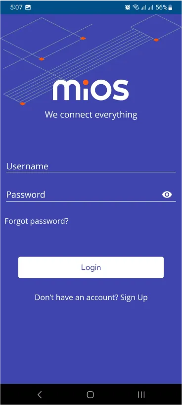
- After downloading the app, proceed to install the application and open it.
- Using the MIOS mobile application, create a new Ezlo Cloud account using the sign-up option. If you already have an account, you may proceed to log in.
- After successfully logging in, you will be able to see the number of controllers connected such as a lamp, fan, or any other device in the MiOS app. Tap on any controller of your desired ID:

- You will be able to see the status of your controller whether it is online or offline. Access the device dashboard, and tap the device. The following view of the dashboard will appear:

- On the MiOS mobile dashboard, you can see that when the Relay_3 is OFF then Relay_1 is OFF and Relay_2 is ON, which means that our DC motor is running in one direction.

- Now, in the MiOS mobile dashboard, you can see that when the Relay_3 is ON then Relay_1 is ON and Relay_2 is OFF, which means that our DC motor is now running in the opposite direction.


