


Two different effects (Android and Bicolor Chase) implementation by interfacing the addressable LED with the EzloPi device.
1. About this example
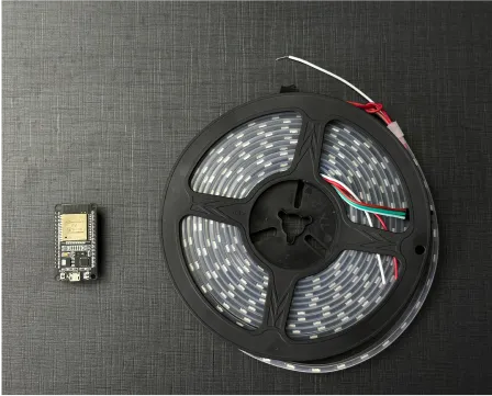
This project demonstrates the interfacing of the addressable LED strips, such as WS2812B, with the ESP32-based EzloPi device. This integration will enable users to control the RGB colors and implement various effects of the LED strips through the EzloPi platform such as the MiOS web and mobile applications. The addressable LED feature adds a dynamic element to smart home environments, enabling users to create immersive lighting effects tailored to different occasions or moods.
Various effects can be set up using the addressable LED strip and EzloPi device as we have demonstrated the two different effects on two different LED segments in this project.
2. Project Video Demonstration
Welcome to the project demonstration video section. The following video showcases the key aspects of ezloPi addressable LED add two segments, providing a visual walkthrough of its implementation.
3. Circuit Setup & Interfacing
The following components are required for interfacing with the EzloPi device:
- EzloPi device (ESP32-based controller board)
- Addressable LED strip (WS2812B, WS2811, SK6812, etc)
- Level shifter module (BSS138)
- 12V to 5V DC-DC Buck Converter (LM2596, etc)
- Power supply for the LED strip (5V/12V)
- Resistor (62 Ohms) (optional)
- Jumper wires
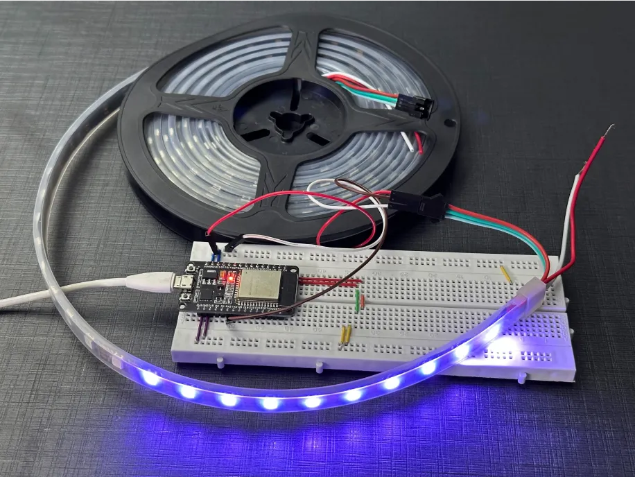
- Breadboard for prototyping (Optional)
Note:
- Ensure that stable output voltages (5V/12V) for both the ESP32 and LED are available.
- When using a level shifter, including a resistor is optional. Additionally, it's worth noting that some LED strips come with an onboard resistor, making its inclusion optional for effective voltage level conversion.
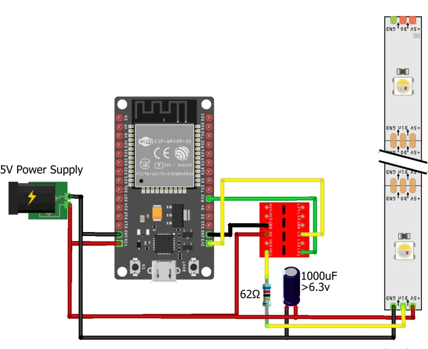
Circuit interfacing and set-up guide:
Connect your RGB LED(whether 5V or 12V) strip’s data pin (Din) to RX2 pin (GPIO16) on ESP32 board
| Addressable LED strip | ESP32 |
| LED Data (Din) | RX2 (GPIO16) |
Connections for 5V LEDs (such as WS2812B):
Following interconnections as shown below are made for interfacing the addressable LED to the EzloPi device:
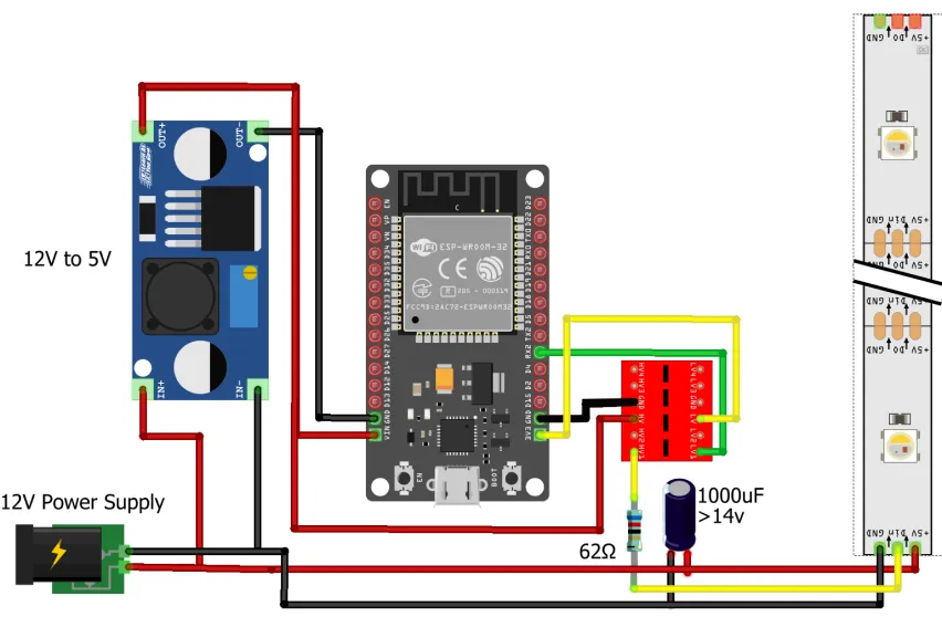
Connections for 12V LEDs (such as WS2811,WS2815 or SK6812):
For LEDs with a 12V power source, a step-down/buck converter is used for converting the 12V to 5V. Make sure that the step-down converter 5V output is stable otherwise try adjusting it using the potentiometer if available.
Following interconnections as shown below are made for interfacing the addressable LED to the EzloPi device:
4. Interfacing the Addressable LED strip using EzloPi Web Flasher:
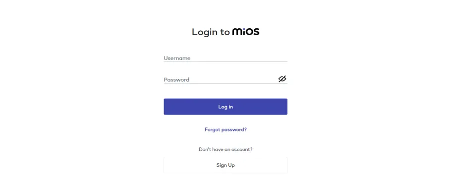
1. First setup your MiOS account by visiting https://www.ezlopi.com/set-up-mios-account and set up your device/hardware by visiting config.ezlopi.com
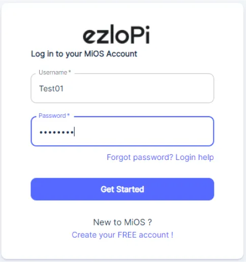
- Log in using the credentials which you just set earlier while signing up.
- Under ezloPi on the top left corner, open the drop down menu.
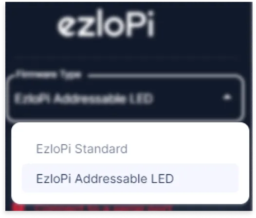
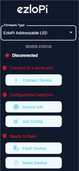
- Select EzloPi Addressable LED.
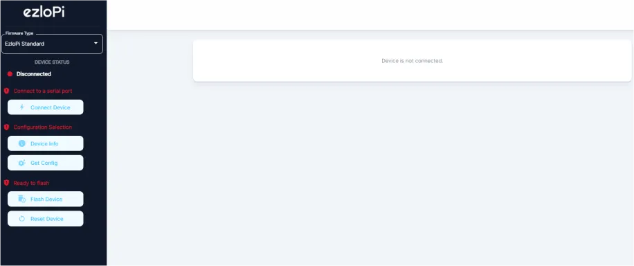
Click Connect.
- Now, click on Connect Device and a pop-up window will appear.
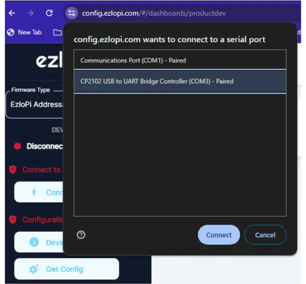
- Now, select COM Port to which your ESP32 device is connected. In our case, the COM3 port is used. Click Connect.
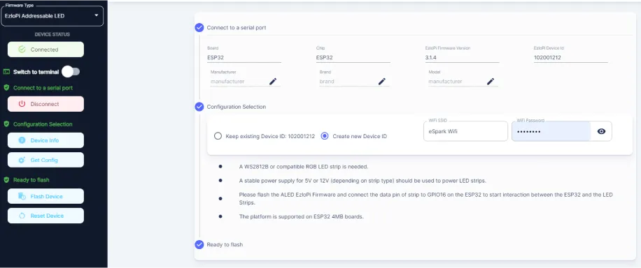
- If you are new to this and it’s your first time configuring, select Create new Device ID. Enter Wifi SSID and Wifi password and then click on Flash Device.
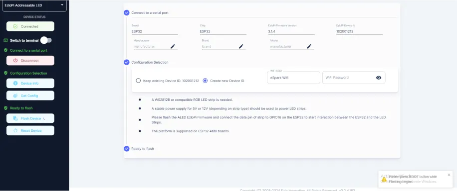
- A window will appear on the bottom left side of the screen displaying “Please press BOOT button while flashing begins.”
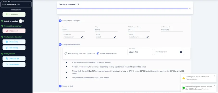
- Hold the BOOT button down until the next window appears on the bottom left side of the screen which says “Installation prepared. Please release the boot button now.”
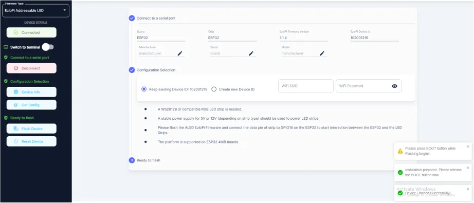
- After some time, a popup will appear on the bottom right hand side of your screen saying Device Flashed Successfully!. This means that your device has been set up successfully.
5. MiOS Web Dashboard
- After configuring the controller with the EzloPi web flasher, head to ezlogic.mios.com
- Use the same credential to log in that you used for configuring the controller with the web flasher.
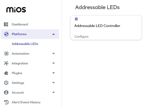
- After login, click on Platforms then click on Addressable LEDs and press Configure.
Note: Make sure your PC and EzloPi device (ESP32) are connected on the same network to enable this function.
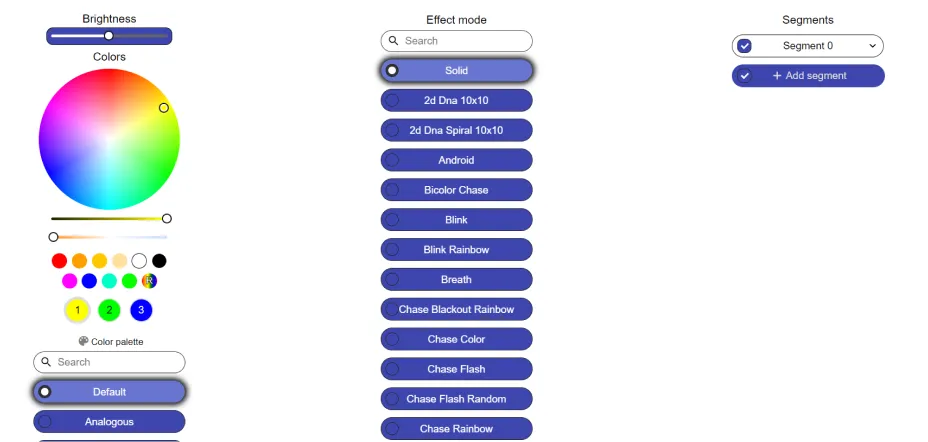
- A new window will open where you can control your RGB LED.
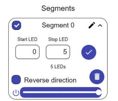
- On the top right side of the screen under Segment 0, you can set the number of LEDs you want to set for specific effect. In our case, we have set it to from 0 to 5. Here we can also set the reverse direction of LEDs which will apply the effect in reverse (from last LED to first). Also brightness control options are also given.
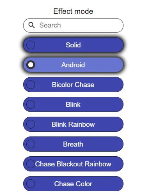
- Under Effect mode, click on Android to apply this effect. By following the above steps, we can successfully implement a android effect using addressable LEDs and the EzloPi smart device, enhancing the visual appeal and versatility of your IoT lighting setup.

- Again, you have to do the same settings for the second segment and effect. First, you have to add a segment, Click on Add segment.
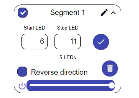
- On the top right side of the screen, Another segment will be added named Segment 1. Under Segment 1, you can set the number of LEDs you want to set for specific effect. In our case, we have set it to 6 to 11. Here we can also set the reverse direction of LEDs which will apply the effect in reverse (from last LED to first). Also brightness control options are also given.
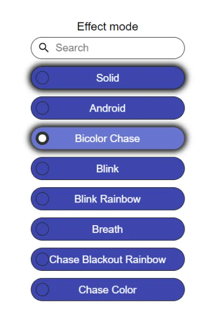
- For the second effect, Under Effect mode, click on Bicolor Chase to apply this effect. By following the above steps, we can successfully implement a bicolor chase effect using addressable LEDs and the EzloPi smart device, enhancing the visual appeal and versatility of your IoT lighting setup.
- From these settings, LEDs from 0 to 5 will show the Android effect and LEDs from 6 to 11 will show the Bicolor Chase effect.


