Unlock the power of motion with seamless integration with EzloPi!


MPU6050 3-Axis Accelerometer & Gyroscope
The EzloPi smart devices provide automation through simple, customizable use with our open-source EzloPi platform, making daily life easier and improving human-machine interactions.
Before moving into this example, it is very important to know about the device registration, provisioning and converting the ESP32 device into an EzloPi device along with knowledge of Web Flasher, MiOS Mobile Application for Android/iOS and the MiOS Web Application.
1. About this example – MPU6050 I2C Tutorial
This example gives us a clear perspective of how the MPU6050 I2C is interfaced with the EzloPi device.
The MPU-6050 sensor module is an Inertial Measurement Unit commonly referred to as ‘IMU’ comprising of a gyroscope and accelerometer integrated together to form a micro-electromechanical system (MEMS) sensor. This sensor is used for precision tracking and measurement of 3D or 3-axis orientation (Roll, Pitch & Yaw) as it interacts with the outside world. When successfully interfaced with the EzloPi device, we can access the accelerometer and gyroscope data from the MPU6050 module using the serial I2C protocols.
2. Project Video Demonstration
Welcome to the project demonstration video section. The following video showcases the key aspects of MPU6050 3-Axis Accelerometer & Gyroscope, providing a visual walkthrough of its implementation.
3. MPU6050 Circuit Setup & Interfacing
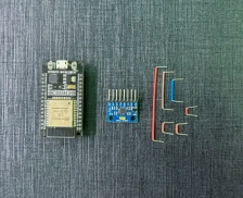
The following components are required for interfacing using the EzloPi device:
- ESP32 as EzloPi smart device.
- MPU6050 3-Axis Accelerometer and Gyroscope Module.
The MPU6050 I2C wiring diagram is represented as follows:
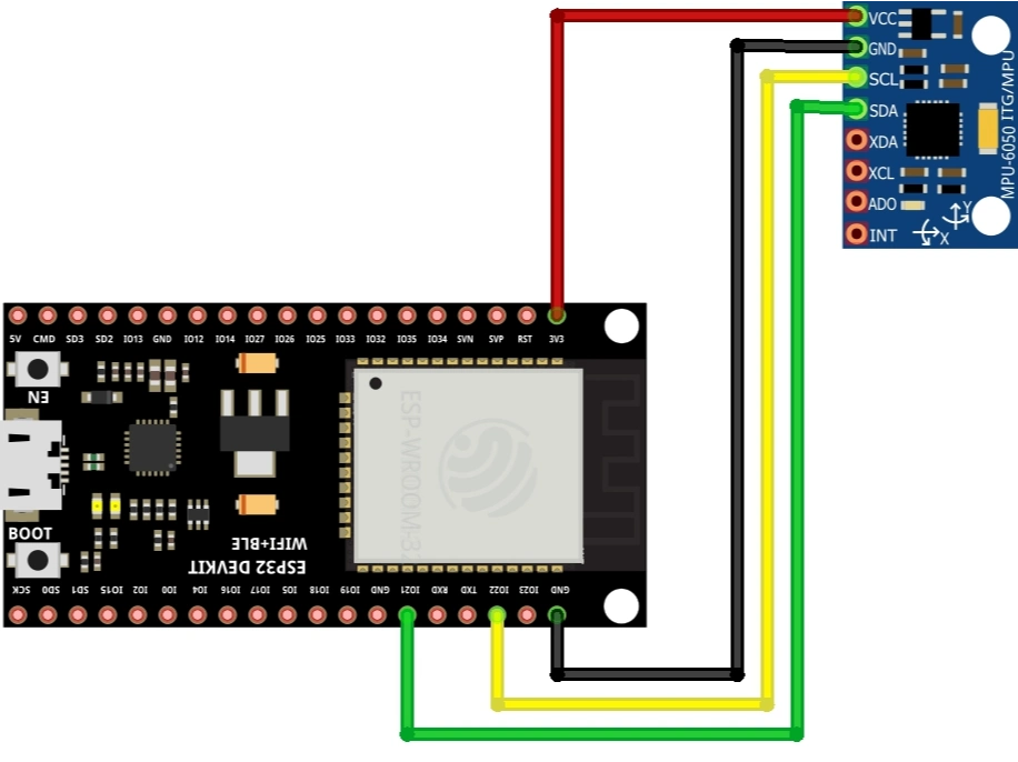
The following connections are made in order to complete the entire MPU6050 I2C circuit setup.
From ESP32 to the MPU6050 module:
- Connect 3v3 pin to the VCC terminal on the MPU6050 module.
- Connect GND to the GND Pin.
- Connect D21 from the ESP to the SDA (Serial Data) pin.
- Connect D22 from the ESP to the SCL (Serial Clock) pin.
4. Interfacing the MPU6050 module using EzloPi Web Flasher
- Set up your device/hardware by visiting config.ezlopi.com
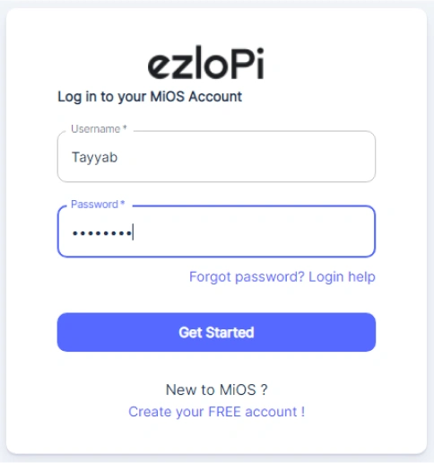
- Log in using the credentials which you just set earlier while signing up.
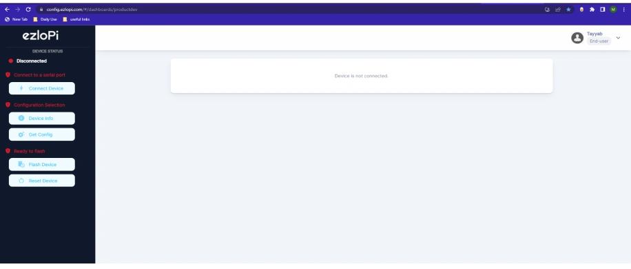
- Now click on Connect Device and a pop-up window will appear
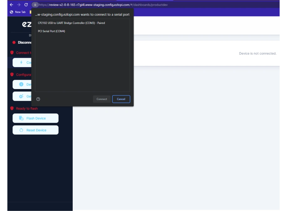
Now, select COM Port to which your ESP32 device is connected. In our case, the COM3 port is used.
Click Connect
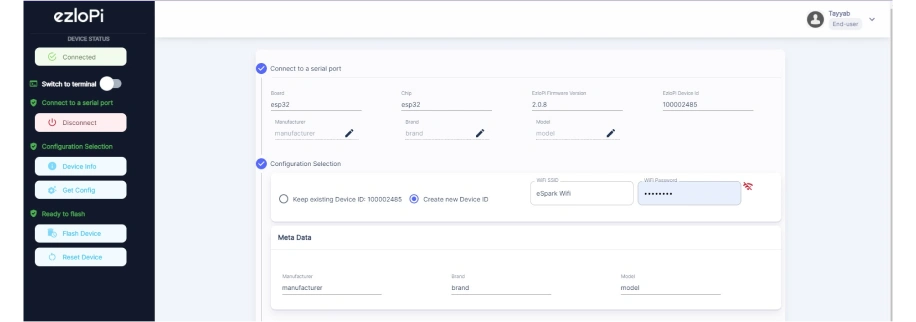
- If you are new to this and it’s your first time configuring, select Create new Device ID. Enter Wifi SSID and Wifi Password.
- In the Device Configuration, tab click on I2C.
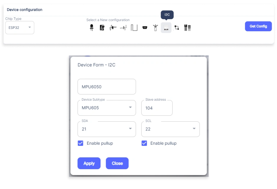
- A pop up window will open for inputting the following parameters.
- Set a device name of your choosing. In our case we set it to Touch
- Set Out GPIO to 4.
- Set Resistor to PULL DOWN.
- Set the default value to low
- Now Click the Apply button.
- After clicking the apply button you can see a table of your setting in the device configuration tab. Press the Flash Device button.
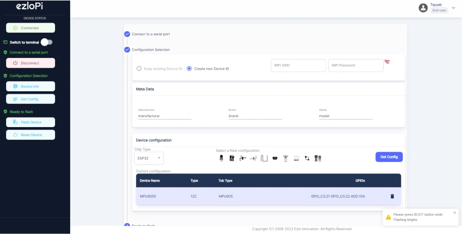
- A window will appear on the bottom left side of the screen displaying “Please press BOOT button while flashing begins.”
- Hold the BOOT button down until the next window appears on the bottom left side of the screen which says “Installation prepared. Please release the boot button now.”
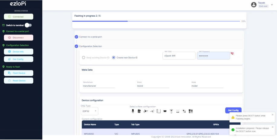
- Release the BOOT button from your ESP32 when this pop-up on the bottom right window appears.
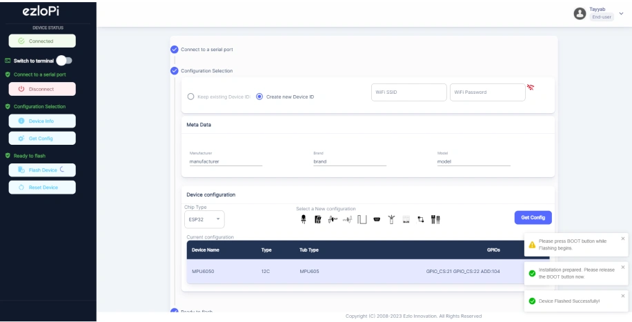
- After some time, a popup will appear saying Device Flashed Successfully! This means that your device has been set up successfully.
5. MiOS App
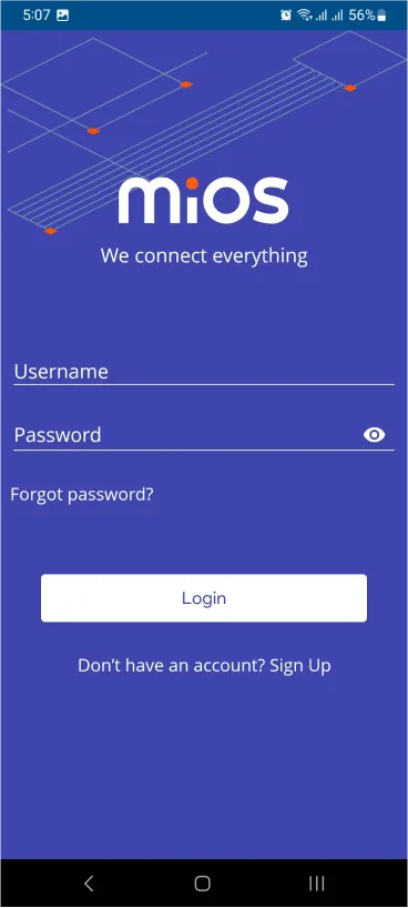
You can download the MIOS Android app from the Google Play Store and Apple App Store.


- After downloading the app, proceed to install the application and open it.

- Using the MIOS mobile application, create a new Ezlo Cloud account using the sign-up option. If you already have an account, you may proceed to log in.
- After successfully logging in, you will be able to see the number of controllers connected such as a lamp, fan, or any other device in the MiOS app. Tap on any controller of your desired ID.
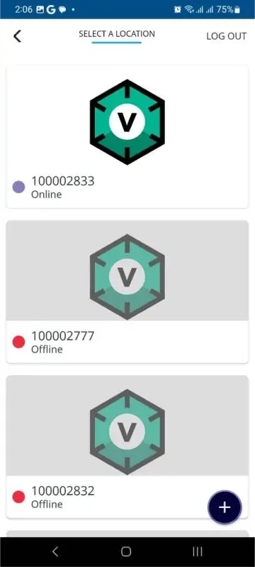
- You will be able to see the status of your controller whether it is online or offline. Access the device dashboard, and tap the device. The following view of the dashboard will appear:
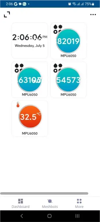
- After opening the dashboard, you will be able to see the tile of your connected device.
- Here, we can see the different tiles representing the values for the x, y and z axes coordinates along with the temperature reading.
When the touch is being detected then it will appear like the figure on the left. And, when the touch is not being detected then it will appear like the figure on the right.
6. MiOS Web Application
- After configuring the controller with the EzloPi web flasher, head to ezlogic.mios.com

- Use the same credentials to log in that you used for configuring the controller with the web flasher.

- In the above figure, it can be seen that the MPU is reflecting the readings of the x-axis, y-axis, z-axis, and the current internal temperature of the silicon die.

- Similarly, when the position of the sensor is changed, the readings of all the 3 axis change respectively.


eZlopie Products A single-channel 5V relay module $00.00

eZlopie Products Momentary switch $00.00

eZlopie Products Level Shifter Module (BSS138) $00.00

eZlopie Products ESP32
$00.00

eZlopie Products AC Lamp and Holder
$00.00