


The EzloPi smart devices provide automation through simple, customizable use with our open-source EzloPi platform, making daily life easier and improving human-machine interactions.
Before moving into this example, it is very important to know about the device registration, provisioning and converting the ESP32 device into an EzloPi device along with knowledge of Web Flasher, MiOS Mobile Application for Android/iOS and the MiOS Web Application.
1. About this example
The goal of this project is to integrate the vibration sensor module with the EzloPi device and also interface LED to provide visual indication, enhancing its capabilities by adding real-time vibration detection functionality and ensuring that each vibration is converted into useful data as in this case a visual aid in the form of the LED, offering a unique aspect to home automation. This combined system will enable users to monitor and respond to sudden impacts or vibrations and motion in the environment. Whether you're looking to increase security, turning your space into a dynamic and responsive environment or create interactive scenarios triggered by motion, EzloPi provides a versatile and convenient solution.
2. Circuit Setup & Interfacing
The following components are required for interfacing using the EzloPi device:
- ESP32 as an EzloPi smart device.
- Vibration sensor module SW-180P.
- 100 Ohm resistor
The wiring diagram is represented as follows:


The following connections are made in order to complete the circuit setup.
From ESP32 to the Vibration sensor module:
| ESP32 | Vibration sensor |
| 3V3 | VIN |
| GND | GND |
| D5 | D0 |
From ESP32 to the LED & Resistor:
| ESP32 | LED | Resistor |
| D4 | Anode | – |
| NA | Cathode | 1st terminal |
| GND | – | 2nd terminal |
3. Interfacing the MQ3 Alcohol sensor module with EzloPi Web Flasher:
1. Set up your device/hardware by visiting config.ezlopi.com
- Log in using the credentials which you just set earlier while signing up.

- Now, click on the Connect Device button and a pop-up window will appear.

Now, select COM Port to which your ESP32 device is connected. In our case, the COM3 port is used.
Click Connect.

- If you are new to this and it's your first time configuring, select Create new Device ID. Enter Wifi SSID and Wifi Password.
- In the Device Configuration, tab click on Digital Input.

- A Digital Input window will open for inputting the following parameters:
- Set a device name of your choosing. In our case we set it to Vibration Sensor.
- Set device Subtype to Vibration Sensor.
- Set Digital input pin to 5.
- Now Click the Apply button.
- Again in the Device Configuration, tab click on Digital Output.

- A Digital output window will open for inputting the following parameters:
- Set a Device name of your choosing. In our case we set it to LED.
- Set Device Subtype to LED.
- Set Digital Output pin to 5.
- Set Resistor to PULL UP.
- Now Click the Apply button.
- After clicking the apply button you can see a table of your setting in the device configuration tab.
- Press the Flash Device button.
- After clicking the apply button you can see a table of your setting below in the Current configuration tab.

- A window will appear on the bottom right side of the screen displaying “Please press BOOT button while flashing begins.”
- Hold the BOOT button down until the next window appears on the bottom right side of the screen which says “Installation prepared. Please release the boot button now.”

- Release the BOOT button from your ESP32 when this pop-up on the bottom right window appears.

- After some time, a popup will appear saying Device Flashed Successfully! This means that your device has been set up successfully.
4. MiOS Web Application
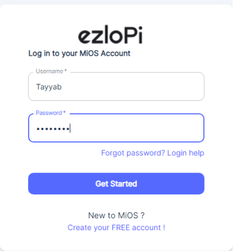
- After configuring the controller with the EzloPi web flasher, head to ezlogic.mios.com
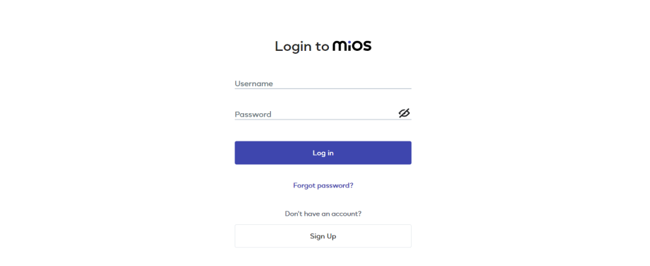
- Use the same credential to log in that you used for configuring the controller with the web flasher.

- On the MiOS web dashboard, you will be able to see the tile for vibration sensor and LED, which is controlled by using the vibration sensor according to rules we have set in the meshbot.
Meshbots

- On the right side of the screen under Automation, click on MeshBots.

- On meshbot screen, click on Create new MeshBot button present on the top right corner of the screen.
- After clicking on Create new MeshBot you will see this now under Automation MeshBot click on Local.

- On the next screen you will see that we can create a name of our choosing, in this case we write it as MQ3.

- In the trigger tab you can set the TRIGGER for your device and in the ACTION tab you can set the action to be performed based on the trigger which you have created.

- Set these things in TRIGGER section:
- Set Node Type to Device.
- Set the Node to Vibration Sensor..
- Set the Capability to Motion.
- Set the value to True.

- Set these values in the TRUE part of the ACTION section.
- Set Controllable Type to Device.
- Set the Controllable to LED.
- Set the Capability to switch.
- Set the Value to true.
- Switch action immediately

- Set these values in the False part of the ACTION section.
- Set Controllable Type to Device.
- Set the Controllable to LED.
- Set the Capability to switch.
- Set the Value to false.
- Switch action immediately to Delay.
- Set Delay to 5 seconds.

- After clicking the save button you can see this screen on the top right corner of the screen.

- Here you can see your saved MeshBot. Now click on Dashboard.

- After opening the MiOS web dashboard, you will be able to see the tile of your connected device. Currently, the tiles are off, which indicates that there is no vibration being detected that is why the LED tile is also shown as OFF.

- Now, we can see that when some vibration is detected, the LED turns ON but it will turn on for 5 secs and then turn off when no motion is detected because of the rules we have set in meshbot.
5. MiOS App
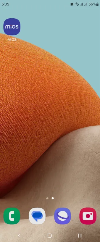
You can download the MIOS Android app from the Google Play Store and Apple App Store.


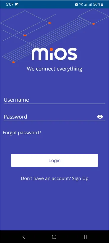
- After downloading the app, proceed to install the application and open it.
- Using the MIOS mobile application, create a new Ezlo Cloud account using the sign-up option. If you already have an account, you may proceed to log in.
- After successfully logging in, you will be able to see the number of controllers connected such as a lamp, fan, or any other device in the MiOS app. Tap on any controller of your desired ID.

- You will be able to see the status of your controller whether it is online or offline. Access the device dashboard, and tap the device. The following view of the dashboard will appear:

- After opening the MiOS mobile app dashboard, you will be able to see the tile of your connected device. Here, as you can see, the sensor tile is displaying a message as “No Motion” when vibrations are not detected by the sensor so the LED is also OFF.

- Similarly, when it detects the vibration, “Motion” appears on the tile and our LED turns ON according to meshbot rules.


