


The EzloPi smart devices provide automation through simple, customizable use with our open-source EzloPi platform, making daily life easier and improving human-machine interactions.
Before moving into this example, it is very important to know about the device registration, provisioning and converting the ESP32 device into an EzloPi device along with knowledge of Web Flasher, MiOS Mobile Application for Android/iOS and the MiOS Web Application.
1. About this example
The LM393 module is a vibration detection sensor that outputs a digital signal when vibrations are detected. It consists of a sensitive component to detect vibrations and an integrated LM393 comparator for signal processing.
The main objective of this project is to create a simple yet effective system for detecting vibrations using the LM393 vibration sensor module and interfacing it with the EzloPi device to monitor the vibrations detected by the sensor. Additionally, an LED is also incorporated as an indicator to visually signal when the sensor detects vibrations. The integration of these components allows for real-time monitoring through the MiOS app, making it suitable for home security applications, industrial applications for monitoring equipment and machinery, and notification systems for seismic activity in earthquake-prone regions, etc.
2. Circuit Setup & Interfacing
The following components are required for interfacing with the EzloPi device:
- ESP32 as an EzloPi smart device.
- LM393 vibration sensor module.
- LED with a current limiting resistor of 82 Ohms.
The wiring diagram for ESP32 is represented as below:

The following connections are made in order to complete the circuit setup:
From ESP32 to Vibration sensor module:
- Connect 3V3 from the ESP32 to the VCC of the module.
- Connect GND from the ESP32 to the GND pin of the module.
- Connect D5 from the ESP32 to the D0 pin of the module.
From ESP32 to the LED:
- Connect the D2 pin from the ESP32 to the LED anode (long leg) through a current limiting resistor of 82 Ohms.
- Connect the GND pin of the ESP32 to the cathode (short leg) of the LED.
3. Interfacing the LDR sensor module with LED using EzloPi Web Flasher
Set up your device/hardware by visiting config.ezlopi.com
- Log in using the credentials which you just set earlier while signing up.

- Now, click on the Connect Device button and a pop-up window will appear.

Now, select COM Port to which your ESP32 device is connected. In our case, the COM3 port is used.
Click Connect.

- If you are new to this and it's your first time configuring, select Create new Device ID. Enter Wifi SSID and Wifi Password.
- In the Device Configuration, tab click on Digital Input.

- A Digital Output window will open for inputting the following parameters:
- Set a device name of your choosing. In our case, we set it to Vibration Sensor.
- Set Device subtype to Relay.
- Set OUT GPIO to 2.
- Set Resistor to PULL UP.
- Set the default value to LOW.
- Check the Button Enable box.
- Set INP GPIO to 5.
- Set Resistor to PULL DOWN.
- Set the default value to LOW.
- Then Click Apply Button.
- After clicking the apply button you can see a table of your setting in the device configuration tab.
- Press the Flash Device button.
- A window will appear on the bottom right side of the screen displaying “Please press BOOT button while flashing begins.”

- Hold the BOOT button down until the next window appears on the bottom right side of the screen which says “Installation prepared. Please release the boot button now.”

- Release the BOOT button from your ESP32 when this pop-up on the bottom right window appears.

- After some time, a popup will appear saying Device Flashed Successfully! This means that your device has been set up successfully.
4. MiOS App
You can download the MIOS Android app from the Google Play Store and Apple App Store.


- After downloading the app, proceed to install the application and open it.
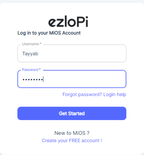
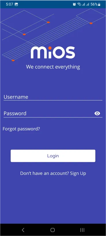
- Using the MIOS mobile application, create a new Ezlo Cloud account using the sign-up option. If you already have an account, you may proceed to log in.
- After successfully logging in, you will be able to see the number of controllers connected such as a lamp, fan, or any other device in the MiOS app. Tap on any controller of your desired ID:

- You will be able to see the status of your controller whether it is online or offline. Access the device dashboard, and tap the device. The following view of the dashboard will appear:

- After opening the MiOS mobile dashboard, you will be able to see the tile of your connected device.
- When the vibrations are not sensed or detected by the vibration sensor module, the vibration sensor tile on the dashboard along with the LED indicator light shows as ‘OFF’.

- But when the vibrations are being sensed or detected by the vibration sensor module, the vibration sensor tile on the dashboard along with the LED indicator light will show as ‘ON’.
5. MiOS Web Application
- After configuring the controller with the EzloPi web flasher, head to ezlogic.mios.com

- Use the same credential to log in that you used for configuring the controller with the web flasher.

- After opening the MiOS web dashboard, you will be able to see the tile of your connected device.
- When the vibrations are not sensed or detected by the vibration sensor module, the vibration sensor tile on the dashboard along with the LED indicator light will show as ‘OFF’.

- But when the vibrations are being sensed or detected by the vibration sensor module, the vibration sensor tile on the web dashboard along with the LED indicator light will show as ‘ON’.


