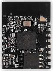
The EPI E03 module features a fully integrated 2.4 GHz radio transceiver and baseband processor for Wi-Fi 802.11b/g/n and Bluetooth® v5.2 IoT applications. It can be used as a stand-alone application-specific communications processor or as a wireless data link in hosted MCU systems where power consumption is critical. It supports flexible memory architecture for storing profiles, stacks and custom application codes and can be updated using Over-The-Air (OTA) technology. The EPI E03 module uses the Beken BK7231N SoC. It is equipped with a powerful 32-bit processor with a clock speed of up to 120 MHz and internal flash memory of 2 MB. EPI E03 can be connected to any external MCU via interface, and to sensors or other devices via GPIO. The transceiver connects directly to the antenna and is fully compatible with Wi-Fi 802.11b/g/n and Bluetooth 5.2 BLE standards. With an integrated antenna switch, RF balun, power amplifier (PA), and low noise amplifier (LNA), the BK7231N enables both Wi-Fi and Bluetooth while minimizing PCB design footprint and external component requirements.
Features
- Built in with the low-power 32-bit CPU, which can also function as an application processor
- Working voltage: 3.0 to 3.6V
- The clock rate: 120 MHz
- Peripherals: 5 PWMs and 1 UART
- Wi-Fi connectivity
- – 802.11 b/g/n
- – Support WEP, WPA/WPA2, WPA/WPA2 PSK (AES), WPA3 security modes
- – Channels 1 to 14@2.4 GHz
- – Up to +16 dBm output power in 802.11b mode
- – Support STA/AP/STA+AP working mode
- – Support SmartConfig and AP network configuration manners for Android and iOS devices
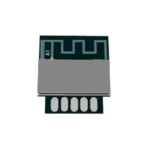
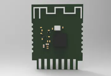
- – Onboard PCB antenna
- – Working temperature: -40°C to 85°C
- Bluetooth connectivity
- – Support the Bluetooth LE V5.2
- – Support the transmit power of 6 dBm in the Bluetooth mode
- – Complete Bluetooth coexistence interface
- – Onboard PCB antenna with a gain of 0 dBi

Pin definition
| Pin N | Symbol | I/O type | Function |
| 1 | P14 | P | Common GPIO, which can be reused as SPI_SCK (Correspond to Pin11 of the IC) |
| 2 | P16 | I/O | Common GPIO, which can be reused as SPI_MOSI (Correspond to Pin12 of the IC) |
| 3 | P20 | P | Common GPIO (Correspond to Pin20 of the IC) |
| 4 | P22 | I/O | Common GPIO (Correspond to Pin18 of the IC) |
| 5 | ADC | I/O | ADC, which corresponds to P23 on the internal IC (Correspond to Pin17 of the IC) |
| 6 | RX2 | I/O | UART2 RX, which corresponds to P1 on the internal IC. (Correspond to Pin28 of the IC |
| 7 | TX2 | I/O | UART2 TX, which is used for outputting logs and corresponds to P0 of the internal IC (Correspond to Pin29 of the IC) |
| 8 | P8 | I/O | Support hardware PWM (Correspond to Pin24 of the IC) |
| 9 | P7 | I/O | Support hardware PWM (Correspond to Pin23 of the IC) |
| 10 | P6 | I/O | Support hardware PWM (Correspond to Pin22 of the IC) |
| 11 | P26 | I/O | Support hardware PWM (Correspond to Pin15 of the IC) |
| 12 | P24 | I/O | Support hardware PWM (Correspond to Pin16 of the IC) |
| 13 | GND | I/O | Power supply reference ground |
| 14 | 3V3 | I/O | Power supply 3V3 |
| 15 | TX1 | I/O | UART1 TX, which is used for transmitting user data and corresponds to Pin27 of the IC. For the MCU solution, please refer to CBx Module |
| 16 | RX1 | I/O | UART1 RX, which is used for receiving user data and corresponds to Pin26 of the IC. For the MCU solution please refer to CBx Module |
| 17 | P28 | I/O | Common GPIO (Correspond to Pin10 of the IC) |
| 18 | CEN | I/O | Reset pin, low active (internally pulled high), compatible with other modules (Correspond to Pin21 of the IC) |
| 19 | P9 | I/O | Common GPIO (Correspond to Pin25 of the IC) |
| 20 | P17 | I/O | Common GPIO, which can be reused as SPI_MISO (Correspond to Pin14 of the IC) |
| 21 | P15 | I/O | Common GPIO, which can be reused as SPI_CS (Correspond to Pin13 of the IC) |
| 22 | CSN | I/O | Mode selection pin. If it is connected to the ground before being powered on, enter the firmware test mode. If it is not connected or connected to VCC before being powered on, enter the firmware application mode. Correspond to Pin19 on the internal IC |
Wi-Fi RF Specification (RX)
| Parameter | Description | Min | Typ | Max | Unit |
| Frequency Range | 2412 | 2484 | MHz | ||
| RX Sensitivity 11g @8% PER | 1 Mbps | -97 | dBm | ||
| 2 Mbps | -93 | dBm | |||
| 5.5 Mbps | -91 | dBm | |||
| 11 Mbps | -89 | dBm | |||
| RX Sensitivity 11g @10% PER | 6 Mbps | -92 | dBm | ||
| 9 Mbps | -90 | dBm | |||
| 12 Mbps | -88 | dBm | |||
| 18 Mbps | -86 | dBm | |||
| 24 Mbps | -82 | dBm | |||
| 36 Mbps | -79 | dBm | |||
| 48 Mbps | -77 | dBm | |||
| 54 Mbps | -75 | dBm | |||
| Receive Sensitivity (11n, 20MHz) @10% PER | MCS=0 | -90 | dBm | ||
| MCS=1 | -88 | dBm | |||
| MCS=2 | -86 | dBm | |||
| MCS=3 | -81 | dBm | |||
| MCS=4 | -79 | dBm | |||
| MCS=5 | -74 | dBm | |||
| MCS=6 | -73 | dBm | |||
| MCS=7 | -71 | dBm |
| Parameter | Description | Min | Typ | Max | Unit |
| Receive Sensitivity (11n, 40MHz) @10% PER | MCS=0 | -88 | dBm | ||
| MCS=1 | -85 | dBm | |||
| MCS=2 | -83 | dBm | |||
| MCS=3 | -78 | dBm | |||
| MCS=4 | -76 | dBm | |||
| MCS=5 | -71 | dBm | |||
| MCS=6 | -70 | dBm | |||
| MCS=7 | -68 | dBm | |||
| Maximum Receive Level | 802.11b | -10 | dBm | ||
| 802.11g | -8 | dBm | |||
| 802.11n | -8 | dBm |
3 Wi-Fi RF Specification (TX)
| Parameter | Condition | Min | Typ | Max | Unit |
| Frequency Range | 2412 | 2484 | MHz | ||
| Outout Power | 802.11b (11Mbps) | 17.0 | dBm | ||
| 802.11g (54Mbps) | 15.0 | dBm | |||
| 802.11n (MCS7) | 14.0 | dBm | |||
| Outout Power | 802.11b (11Mbps) | -15 | -10 | dB | |
| 802.11g (54Mbps) | -28 | -25 | dB | ||
| 802.11n (MCS7) | -30 | -28 | dB | ||
| VBAT=3.3V, Ambient temperature=25°C | |||||
Power Consumption
| Parameter | Condition | Min | Typ | Max | Unit |
| Continuous TX | 802.11b/11Mbps/17dB, | 280 | mA | ||
| Continuous TX | 802.11g/54Mbps/15dB, | 250 | mA | ||
| Continuous TX | 802.11n/HT20-MCS7/14dB, | 250 | mA | ||
| RX mode | 802.11b/11Mbps/-10dB input | 63 | mA | ||
| RX mode | 802.11g/54Mbps/-10dB input | 69 | mA | ||
| RX mode | 802.11n/HT20-MCS7/-10dB input | 69 | mA | ||
| Normal Standby | MCU stop; Modem power-off | 30 | uA | ||
| Low-power Standby | MCU stop in low-power mode | 10 | uA | ||
| Deep Sleep | All main logic circuit power-off | 5 | uA | ||
| Shutdown | CEN pin = LOW | 1 | uA |
BLE RF Specification (RX)
| Parameter | Condition | Min | Typ | Max | Unit |
| Frequency Range | 2402 | 2480 | MHz | ||
| RX Sensitivity | -85 | dBm | |||
| Maximum Input Level | -10 | dBm |
BLE RF Specification (TX)
| Parameter | Condition | Min | Typ | Max | Unit |
| Frequency Range | 2402 | 2480 | MHz | ||
| Maximum Output Power | -20 | 5 | 18 | dBm | |
| 20dB Bandwidth | 1 | MHz |