This user guide provides information about Ezlobord, a small-sized ESP32 datasheet-based development and simulation board manufactured by Ezlo
Overview
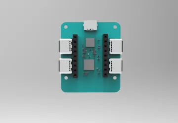
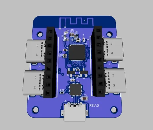
Ezlobord is a small ESP32 based development board manufactured by Ezlo. Most of the I/O pins are routed to contact connectors and connected to USB Type-C connectors on both sides to simplify interaction with connected devices. Developers can either connect peripherals using jumpers or a USB Type-C cable to the expansion card.
Block Diagram

Power options
There are three mutually exclusive ways to supply power to the board:
- Micro-USB port, default power supply
- 5V and GND pin headers
- 3V3 and GND pin connectors
- It is recommended to use the first option: Micro-USB port.
Overview
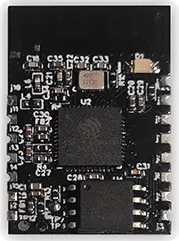
Ezlobord is a general-purpose Wi-Fi+Bluetooth®+Bluetooth LE board designed for a wide range of applications, from low-power network sensors to the most complex applications such as voice encoding, music streaming and MP3 decoding. This module is based on the ESP32-D0WDQ6* chip. The embedded chip is designed to scale and adapt. There are two CPU cores that can be controlled individually, and the CPU clock speed can be adjusted between 160 MHz and 240 MHz. The chip also has a low-power coprocessor that can be used in place of the CPU to save power when performing tasks that are not compute-intensive. Ezlobord has a rich set of peripherals, including capacitive touch sensors, SD card interfaces, Ethernet, high-speed SPI, UART, I2S and I2C
CPU and OnChip Memory
- ESP32-U4WDH embedded, Xtensa dual-core
- 32-bit LX6 microprocessor, up to 240 MHz
- 448 KB ROM
- 520 KB SRAM
- 16 KB SRAM in RTC
- 128M-BIT SPI flash
CrystalOscillators Themoduleusesa40-MHzcrystaloscillator.
Wi-Fi
- 802.11b/g/n
- Bit rate: 802.11n up to 150 Mbps
- A-MPDU and A-MSDU aggregation
- 0.4 µs guard interval support
- Center frequency range of operating channel:
- 2412 ~ 2484 MHz
- 128M-BIT SPI flash
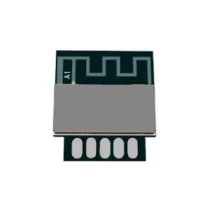
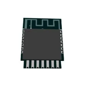
Antenna Options
- ESP32: On-board PCB antenna
Bluetooth
- Bluetooth v4.2 BR/EDR and Bluetooth LE specification
- Class-1, class-2, and class-3 transmitter
- AFH
- CVSD and SBC
Operating Conditions
- Operating voltage/Power supply: 3.0 ~ 3.6 V
Operating ambient temperature:
- 85 °C version module: –40 ~ 85 °C
- 105 °C version module: –40 ~ 105 °C
Module Interfaces
2.1 Dimensions and footprint
has two rows of pins with a 2± 0.1 mm pin spacing. The Ezlobord dimensions are 34 mm (W)×40mm (L)
J7
| N0 | Name | Type | Function |
|---|---|---|---|
| 1) | +5V | P | |
| 2) | +3,3V | P | |
| 3) | IO27 | GPIO27 | ADC2_CH7 |
| 4) | IO16 | GPIO16 | ADC2_CH6 |
| 5) | IO17 | GPIO17 | DAC_2 ADC2_CH9 |
| 6) | IO4 | GPIO4 | HS2_DATA1 SD_DATA1 EMAC_TX_ER |
| 7) | IO26 | GPIO26 | EMAC_RXD1 |
| 8) | IO25 | GPIO25 | EMAC_RXD0 |
| 9) | Gnd | P |
J5
| N0 | Name | Type | Function |
|---|---|---|---|
| 1) | +5V | P | |
| 2) | +3,3V | P | |
| 3) | IO5 | GPIO5 | VSPICS0 HS1_DATA6 – EMAC_RX_CLK |
| 4) | IO18 | GPIO18 | VSPICLK HS1_DATA7 |
| 5) | IO23 | GPIO23 | VSPID HS1_STROBE |
| 6) | IO19 | GPIO21 | VSPIHD EMAC_TX_EN |
| 7) | IO22 | GPIO22 | VSPIWP U0RTS – EMAC_TXD1 |
| 8) | IO21 | GPIO21 | VSPIHD EMAC_TX_EN |
| 9) | GND | P |
J1, J4
| N0 | Name1 | Name2 |
|---|---|---|
| 1) | A1 | Gnd |
| 2) | A2 | GPIO25 |
| 3) | A3 | GPIO26 |
| 4) | A4 | +5V |
| 5) | A6 | GPIO4 |
| 6) | A7 | GPIO27 |
| 7) | A9 | +5V |
| 8) | A10 | GPIO4 |
| 9) | A11 | GPIO17 |
| 10) | A12 | GND |
J2, J3
| N0 | Name1 | Name2 |
|---|---|---|
| 1) | A1 | Gnd |
| 2) | A2 | GPIO5 |
| 3) | A3 | GPIO18 |
| 4) | A4 | +5V |
| 5) | A6 | GPIO23 |
| 6) | A7 | GPIO19 |
| 7) | A9 | +5V |
| 8) | A10 | GPIO22 |
| 9) | A11 | GPIO21 |
3. Electrical parameters
3.1 Absolute Maximum Ratings
| Parameter | Description | Min | Max | Unit |
|---|---|---|---|---|
| VDDA, VDD3P3, VDD3P3_RTC, VDD3P3_CPU, VDD_SDIO | Allowed input voltage | –0.3 | 3.6 | V |
| Ioutput* | Cumulative IO output current(1) | – | 1200 | mA |
| TSTORE | Storage temperature | –40 | 150 | °C |
*The product proved to be fully functional after all its IO pins were pulled high while being connected to ground for 24 consecutive hours at ambient temperature of 25 °C
Recommended Power Supply Characteristics
| Parameter | Description | Min | Type | Max | Unit |
|---|---|---|---|---|---|
| VDDA, VDD3P3_RTC , VDD3P3, VDD_SDIO (3.3 V mode) | Voltage applied to power supply pins per power domain | 2.3/3.0 | 3.3 | 3.6 | V |
| VDD3P3_CPU | Voltage applied to power supply pin | 1.8 | 3.3 | 3.6 | V |
| IVDD | Current delivered by external power supply | 0.5 | – | – | A |
| T | Operating temperature | –40 | – | 125 | °C |
3.2 DC Characteristics (3.3 V, 25 °C)
| Parameter | Description | Min | Type | Max | Unit | |
|---|---|---|---|---|---|---|
| CIN | Pin capacitance | — | 2 | — | pF | |
| VIH | High-level input voltage | 0.75×VDD | — | VDD+0.3 | V | |
| VIL | Low-level input voltage | –0.3 | — | 0.25×VDD | v | |
| IIH | Low-level input voltage | — | — | 50 | nA | |
| IIL | High-level input current | — | — | 50 | nA | |
| VOH | High-level output voltage | — | — | — | V | |
| VOL | Low-level output voltage | — | — | 0.1×VDD | V | |
| IOH | High-level source current (VDD1 = 3.3 V, VOH >= 2.64 V, output drive strength set to the maximum) | VDD3P3_CPU power domain | — | 40 | — | mA |
| VDD3P3_RTC power domain | — | 40 | — | mA | ||
| VDD_SDIO power omain | — | 20 | — | mA | ||
| IOL | Low-level sink current (VDD1= 3.3 V, VOL = 0.495 V, output drive strength set to the maximum | — | 28 | — | mA | |
| RPU | Resistance of internal pull-up resistor | — | 45 | — | kΩ | |
| RPD | Resistance of internal pull-down resistor | — | 45 | — | kΩ | |
| VIL_nRS | Low-level input voltage of CHIP_PU to shut down the chip | — | — | 0.6 | V | |
3.3 RF Current Consumption in Active Mode Current Consumption Depending on RF Modes
| Work Mode | Min | Type | Max | Unit |
|---|---|---|---|---|
| Transmit 802.11b, DSSS 1 Mbps, POUT = +19.5 dBm | — | 240 | — | mA |
| Transmit 802.11g, OFDM 54 Mbps, POUT = +16 dBm | td>—190 | — | mA | |
| Transmit 802.11n, OFDM MCS7, POUT = +14 dBm | — | 180 | — | mA |
| Receive 802.11b/g/n | — | 95 ~ 100 | — | mA |
| Transmit BT/BLE, POUT = 0 dBm | — | 130 | — | mA |
| Receive BT/BLE | — | 95 ~ 100 | — | mA |
3.4 Wi-Fi Radio Characteristics
| Parameter | Description | Min | Type | Max | Unit |
|---|---|---|---|---|---|
| Operating frequency range | — | 2412 | — | 2484 | MHz |
| Output impedance | — | — | 30+j10 | — | Ω |
| TX power | 11n, MCS7 | 12 | 13 | 14 | dBm |
| 11b mode | 18.5 | 19.5 | 20.5 | dBm | |
| Output impedance | 11b, 1 Mbps | — | –98 | — | dBm |
| 11b, 11 Mbps | — | –88 | — | dBm | |
| 11g, 6 Mbps | — | –93 | — | dBm | |
| 11g, 54 Mbps | — | –75 | — | dBm | |
| 11n, HT20, MCS0 | — | –93 | — | dBm | |
| 11n, HT20, MCS7 | — | –73 | — | dBm | |
| 11n, HT40, MCS0 | — | –90 | — | dBm | |
| 11n, HT20, MCS7 | — | –70 | — | dBm | |
| Adjacent channel rejection | 11g, 6 Mbps | — | 27 | — | dB |
| 11g, 54 Mbps | — | 13 | — | dB | |
| 11n, HT20, MCS0 | — | 27 | — | dB | |
| 11n, HT20, MCS7 | — | 12 | — | dB |