BLE; BLE Mesh; 6LoWPAN; Zigbee; RF4CE; 2.4GHz
RF Features RF features include:
- BLE/802.15.4/2.4GHz RF transceiver embedded, working in worldwide 2.4GHz ISM band.
- Bluetooth LE 1Mbps and 2Mbps, Long Range 125kbps and 500kbps.
- IEEE802.15.4 compliant, 250kbps.
- 2.4GHz proprietary 1Mbps/2Mbps/250kbps/500kbps mode with Adaptive Frequency Hopping feature support.
- Rx Sensitivity: -96dBm@BLE 1Mbps, -99.5dBm@ IEEE802.15.4 250kbps, -93dBm @ BLE 2Mbps mode, -99dBm @ BLE 500kbps mode, -101dBm @ BLE 125kbps mode.
- Tx output power: up to +10dBm.
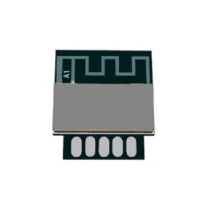
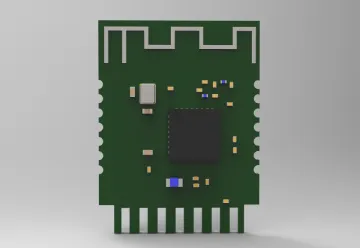
- Single-pin antenna interface.
- RSSI monitoring with +/-1dB resolution.
- Auto acknowledgement, retransmission and flow control.
- Support full-function BLE location features.
Features of power management module Features of power management module include:
- Embedded DCDC.
- Battery monitor: Supports low battery detection.
- Power supply: 1.8V~3.6V.
- Multiple stage power management to minimize power consumption.
Low power consumption:
- Whole Chip RX mode: 5.3mA
- Whole Chip TX mode: 4.8mA @ 0dBm with DCDC
- Deep sleep with external wakeup (without SRAM retention): 0.4uA
- Deep sleep with SRAM retention: 1uA (with 8kB SRAM retention), 1.2uA (with 16kB SRAM retention), 1.4uA (with 32kB SRAM retention)
Zigbee features Zigbee features include:
- Based on IEEE 802.15.4 Standard, certified Zigbee Pro and Zigbee 3.0 platform, with ZHA/ZLL profile and Zigbee 3.0 device support.
- Uses multi-hop mesh networking to eliminate single points of failure and expand the reach of networks.
- Allow low power operation, even support the Green Power feature.
- Supports networks of thousands of nodes, providing a networking for the smart home or the smart city.
- Uses a variety of security mechanisms, such as AES-128 encryption, device and network keys and frame counters.
- Include all application level functionality of ZigBee Smart Energy.
- Support seamless interoperability with a wide variety of smart devices.
- Over the air (OTA) firmware upgrade with hardware support.
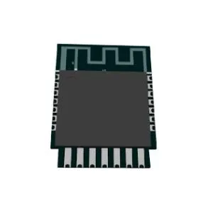
Pin definition:

| Pin number | Symbol | I/O type | Function |
|---|---|---|---|
| 1 | D3 | I/O | Common I/O pin, which corresponds to D3 (Pin 32) of IC |
| 2 | D7 | I/O | Common I/O pin, which corresponds to D7 (Pin 2) of IC |
| 3 | C0 | I/O | Common I/O pin, which corresponds to C0 (Pin 20) of IC |
| 4 | SWS | I/O | Burning pin, which corresponds to SWS (Pin 5) of IC |
| 5 | ADC | I/O | ADC pin, which corresponds to B6 (Pin 16) of IC |
| 6 | A0 | I/O | Common I/O pin, which corresponds to A0 (Pin 3) of IC |
| 7 | A1 | I/O | Common I/O pin, which corresponds to A1 (Pin 4) of IC |
| 8 | C2 | I/O | Support hardware PWM and correspond to C2 (Pin 22) on the internal IC |
| 9 | C3 | I/O | Support hardware PWM and correspond to C3 (Pin 23) on the internal IC |
| 10 | D2 | I/O | Support hardware PWM and correspond to D2 (Pin 31) on the internal IC |
| 11 | B4 | I/O | Support hardware PWM and correspond to B4 (Pin 14) on the internal IC |
| 12 | B5 | I/O | Support hardware PWM and correspond to B5 (Pin 15) on the internal IC |
| 13 | GND | I/O | Power supply reference ground |
| 14 | VCC | I/O | Power supply pin (3.3V) 15 B1 I/O Uart_TXD, which corresponds to B1 (Pin 6) of IC |
| 16 | B7 | I/O | Uart_RXD, which corresponds to B7 (Pin 17) of IC 17 C4 I/O ADC pin, which corresponds to C4 (Pin 16) of IC |
| 18 | RST | I/O | Reset pin, active low |
| 19 | C1 | I/O | Common I/O pin, which corresponds to C1 (Pin 21) of IC |
| 20 | D4 | I/O | Common I/O pin, which correspondsto D4 (Pin 1) of IC |
| 21 | NC | I/O | No connection |
Antenna interference reduction
To ensure the optimal Zigbee performance when the Zigbee module uses an onboard
PCB antenna, it is recommended that the antenna be at least 15 mm away from other metal parts.
To prevent an adverse impact on the antenna radiation performance, avoid copper
or traces along the antenna area on the PCB.